Friday, November 9, 2018
There are other container platforms besides Docker? Like LXC?
I'm relatively new to containers technology. I didn't even realize there were alternatives to Docker (although I hadn't really thought about it).
Colleague of mine knew this though, and sent me this interesting link.
https://robin.io/blog/linux-containers-comparison-lxc-docker/
This link is a discussion about a more powerful container platform called LXC, which could be used as an alternative to Docker.
I'm still in the process of learning about it. Will update the blog later.
Wednesday, October 31, 2018
Data Plane Development Kit (DPDK)
I kept noticing that a lot of the carrier OEMs are implementing their "own" Virtual Switches.
I wasn't really sure why, and decided to look into the matter. After all, there is a fast-performing OpenVSwitch, which while fairly complex, is powerful, flexible, and, well, open source.
Come to learn, there is actually a faster way to do networking than with native OpenVSwitch.
OpenVSwitch minimizes all of the context switching between user space and kernel space when it comes to taking packets from a physical port, and forwarding those packets to virtualized network functions (VNF) and back.
But - DPDK provides a means to circumvent the kernel, and have practically everything in user space interacting directly to the hardware (bypassing the kernel).
This is fast, indeed, if you can do this. But it bypasses all of the purposes of a kernel network stack, so there has to be some sacrifice (which I need to look into and understand better). One of the ways it bypasses the kernel is through Direct Memory Access (DMA), based on some limited reading (frankly, reading it and digesting it and understanding it usually requires several reads and a bit of concentration as this stuff gets very complex very fast).
The other question I have, is that if DPDK is bypassing the kernel en route to a physical NIC, what about other kernel-based networking services that are using that same NIC? How does that work?
I've got questions. More questions.
But up to now, I was unaware of this DPDK and its role in the new generation of virtual switches coming out. Even OpenVSwitch itself has a DPDK version.
Sunday, October 28, 2018
Service Chaining and Service Function Forwarding
I had read about the concept of service chaining and service forward functioning early on, in a SD-WAN / NFV book that I had read, which at the time was ahead of its time. I hadn't actually SEEN this, or implemented it, until just recently on my latest project.
Now, we have two "Cloud" initiatives going on at the moment, plus one that's been in play for a while.
Now, we have two "Cloud" initiatives going on at the moment, plus one that's been in play for a while.
- Ansible - chosen over Puppet, and Chef in a research initiative, this technology is essentially used to automate the deployment and configurations of VMs (LibVirt KVMs to be accurate).
- But there is no service chaining or service function forwarding in this.
- OpenStack / OpenBaton - this is a project to implement Service Orchestration - using ETSI MANO descriptors to "describe" Network Functions, Services, etc.
- But we only implemented a single VNF, and did not chain them together with chaining rules, or forwarding rules.
- Kubernetes - this is a current project to deploy technology into containers. And while there is reliance and dependencies between the containers, including scaling and autoscaling, I would not say that we have implemented Service Chaining or Service Function Forwarding the way it was conceptualized academically and in standards.
The latest project I was involved with DID make use of Service Chaining and Service Function Forwarding. We had to deploy a VNF onto a Ciena 3906mvi device, which had a built-in Network Virtualization module that ran on a Linux operating system. This ran "on top" of an underlying Linux operating system that dealt with the more physical aspects of the box (fiber ports, ethernet ports both 1G and 100G, et al).
It's my understanding that the terms Service Chaining and Service Function Forwarding have their roots in the YANG reference model. https://en.wikipedia.org/wiki/YANG
This link has a short primer on YANG.
YANG is supposed to extend a base set of network operations that are spelled out in a standard called NETCONF (feel free to research this - it and YANG are both topics in and of themselves).
In summary, it was rather straightforward to deploy the VNF. You had to know how to do it on this particular box, but it was rather straightforward. What was NOT straightforward, was figuring out how you wanted your traffic to flow, and configuring the Service Chaining and Service Function Forwarding rules.
What really hit home to me is that the Virtual Switch (fabric) is the epicenter of the technology. Without knowing how these switches are configured and inter-operate, you can't do squat - automated, manual, with descriptors, or not. And this includes troubleshooting them.
Now with Ciena, theirs on this box was proprietary. So you were configuring Flooding Domains, Ports, Logical Ports, Traffic Classifiers, VLANs, etc. This is the only way you can make sure your traffic is hop-scotching around the box the way you want it to, based on rules you specify.
Here is another link on Service Chaining and Service Function Forwarding that's worth a read.
Monday, October 15, 2018
Kubernetes Part VI - Helm Package Manager
This past week, my colleague has introduced me to something called Helm, which is sort of like a "pip" for Python. It manages Kubernetes packages (it is a Kubernetes Package Manager).
The reason this was introduced:
We found SEVERAL github repos with Prometheus Metrics in them, and they were not at all consistent.
This meant I had to understand what Helm is. Helm is divided into a client (Helm), a server (Tiller), and you install packages (Charts). I guess it's a maritime themed concept, although I don't know why they can't call a package a package (copyright reasons maybe?).
So - I installed Helm, and that went smoothly enough. I installed it on my Kubernetes Master. I also downloaded a bunch of Charts off the stable release in GitHub (Prometheus is one of these). These all sit in a /stable directory (after the git clone, ./charts/stable).
When I came back in, and wanted to pick back up, I wasn't sure if I had installed Prometheus or not. So I ran a "helm list", and got the following error:
Error: configmaps is forbidden: User "system:serviceaccount:kube-system:default" cannot list configmaps in the namespace "kube-system"
Yikes. For a newbie, this looked scary. Fortunately Google had a fix for this on a StackOverflow page.
I had to run these commands:
But, more importantly, I really need to take some time to understand what we just ran above, with regards to this stuff above; the cluster role bindings, et al.
The reason this was introduced:
We found SEVERAL github repos with Prometheus Metrics in them, and they were not at all consistent.
- Kubernetes had one
- There was another one at a stefanprod project
- There was yet a third called "incubator"
This meant I had to understand what Helm is. Helm is divided into a client (Helm), a server (Tiller), and you install packages (Charts). I guess it's a maritime themed concept, although I don't know why they can't call a package a package (copyright reasons maybe?).
So - I installed Helm, and that went smoothly enough. I installed it on my Kubernetes Master. I also downloaded a bunch of Charts off the stable release in GitHub (Prometheus is one of these). These all sit in a /stable directory (after the git clone, ./charts/stable).
When I came back in, and wanted to pick back up, I wasn't sure if I had installed Prometheus or not. So I ran a "helm list", and got the following error:
Error: configmaps is forbidden: User "system:serviceaccount:kube-system:default" cannot list configmaps in the namespace "kube-system"
Yikes. For a newbie, this looked scary. Fortunately Google had a fix for this on a StackOverflow page.
I had to run these commands:
kubectl create serviceaccount --namespace kube-system tiller
kubectl create clusterrolebinding tiller-cluster-rule --clusterrole=cluster-admin --serviceaccount=kube-system:tiller
kubectl patch deploy --namespace kube-system tiller-deploy -p '{"spec":{"template":{"spec":{"serviceAccount":"tiller"}}}}'
helm init --service-account tiller --upgrade But, more importantly, I really need to take some time to understand what we just ran above, with regards to this stuff above; the cluster role bindings, et al.
Thursday, October 11, 2018
What is a Flooding Domain?
I have been working on configuring this Ciena 3906MVI premise router, with a Virtualized Network Function (VNF), and connecting that VNF back to some physical network ports.
This is a rather complex piece of hardware (under the hood).
I noticed in some commands, they were creating these Flooding Domains. And I didn't know what those were (there were sub-types called VPWS and VPLS and I need to look into that as well).
These Flooding Domains are then associated with "classifiers", like "Ingress Classifiers".
I didn't truly know what a Flooding Domain was. Not a lot on the web if you search those two words together. There's plenty of stuff on the concept of Flooding, however.
I found a link where someone asked what the difference between Flooding and Broadcasting is, and it is in this link where I found the best clues to get the proper understanding. So I will recap that there:
https://networkengineering.stackexchange.com/questions/36662/what-is-the-difference-between-broadcasting-and-flooding
What is the Difference between Broadcasting and Flooding?
Broadcasting is a term that is used on a broadcast domain, which is bounded by layer-3 (routers). Broadcasts are sent to a special broadcast address, both for layer-2 and layer-3. A broadcast cannot cross a layer-3 device, and every host in a broadcast domain must be interrupted and inspect a broadcast.
Flooding is used by a switch at layer-2 to send unknown unicast frames to all other interfaces. If a frame is not destined for a host which receives it, the host will ignore it and not be interrupted. This, too, is limited to a broadcast domain.
Flooding in OSPF (layer-3) means that the routes get delivered to every OSPF router in an area. It really has nothing to do with a broadcast. OSPF doesn't use broadcasts to send routes, it uses unicast or multicast to connect with its neighbors. Each OSPF router needs to have a full understanding of all the routers and routes in its area, and it tells all its neighbors about all its local routes, and any routes it hears about from other neighbors. (OSPF routers are unrepentant gossips.)
So, a Flooding Domain is essentially a "domain of packet delivery" - where the point of the inbound (ingress) packet is not where the packet exits (egress). That's my best definition.Friday, September 21, 2018
Can ETSI-MANO Architecture Framework work with Kubernetes?
This rather simple question has been difficult to answer.
The ONLY reference on the web about this, is a PDF I found that discusses using "Containerized" OpenStack, with OPNFV.
What is not clear to me, is whether this solution uses the "standards-based" descriptors, such as Network Service Descriptors (NSD), etc.
I finally went out on the OpenBaton board on Gitter and asked about this. Makes sense to hear what they have to say (if they respond) before we invest time going down that road.
Ideally, the Kubernetes would be a "VIM", I think, rather than an Openstack "VIM".
But I'm not sure. I need some help on this one.
Kubernetes Networking - A More In-Depth look
I see a lot of people using Flannel, and Weave-Net for their Kubernetes Networking implementations.
I came across a reasonable attempt to explain the distinctions between them at this blog here:
https://chrislovecnm.com/kubernetes/cni/choosing-a-cni-provider/
I think there were about ten or twelve listed there, but Flannel and Weave-Net are the two most prevalent ones.
Flannel has more Git activity currently, but in terms of robustness and features, Weave-Net apparently has more of that, while Flannel has simplicity.
There is no shortage of good blogs out there on how these work, but this one link I came across had some nice packet flows, and those aren't easy to do, so I will show those here for future reference (for me or anyone else that consults this blog).
Here is Part I:
https://medium.com/@ApsOps/an-illustrated-guide-to-kubernetes-networking-part-1-d1ede3322727
In Part I, this packet flow is irrespective of which particular Kubernetes network implementation you use. In other words, this flow is "Kubernetes Centric". It deals with how pods inter-communicate with each other on a single node, and how pods intercommunicate with each other across nodes.
One of the main aspects is that all nodes in a Kubernetes cluster get a routing table that is updated with the pod CIDRs.
NOTE: This does not address pods going out of Kubernetes and back into Kubernetes. Something I need to look into.
and Part II:
https://medium.com/@ApsOps/an-illustrated-guide-to-kubernetes-networking-part-2-13fdc6c4e24c
In Part II, he shows how a Flannel overlay network "bolts on" to the networking implementation in Part I above. Flannel uses a "flannel0" interface that essentially encapsulates and tunnels packets to the respective pods. A daemon, flanneld, consults Kubernetes for the tunneling information that it uses when it adds source and destination ip addresses for the pods that packets need to be delivered to.
Docker: Understanding Docker Images and Containers
So this week has been emphasized on understanding how Docker works.
First, I learned about Docker images - how to create images, etc.
There is a pretty good blog that can be used to get going on this topic, which can be found here:
https://osric.com/chris/accidental-developer/2017/08/running-centos-in-a-docker-container/
Docker images are actually created in Layers. So you generally start off by pulling in a docker container image for centos, and then running it.
This is done as follows;
# docker pull centos
# docker run centos
# docker image ls
Note: If you run "docker container ls" you won't see it because it's not running and therefore not containerized. Once you run the container image, THEN it becomes containerized and you can run "docker container ls" and you will be able to see it.
# docker run -it centos
Once you run the image, you are now "in" the container and you get a new prompt with a new guid, as shown below:
[root@4f0b435cbdb6 /]#
Now you can make changes to this image as you see fit; yum install packages, copy things into a running container by using the "docker cp" command.
Once you get a container the way you want it, you can exit that container, and then use the guid of that container (don't lose it!) to "commit" it.
Once committed, you need to push it to a registry.
Registries are another topic. If you use Docker Hub (https://hub.docker.com), you need to create an account, and you can create a public repository or a private repository. If you use a private one, you need to authenticate to use it. If you use a public one, anyone can see, take or use whatever you upload.
JFrog is another artifact repository that can be used.
Ultimately what we wound up doing, is creating a new local registry in a container by using the following command:
# docker run -d -p 5000:5000 --restart=always --name registry registry:2
Then, you can push your newly saved container images to this registry by using a command such as:
# docker push kubernetes-master:5000/centos-revised-k8s:10
So essentially we did the push to a specific host (kubernertes-master), on port 5000, and gave it the image name and a new tag.
Friday, September 14, 2018
Jumping into Kubernetes without understanding Docker and Containers
Clearly, it's best to understand Containers and Docker before you jump right into the deep water of Kubernetes.
I went in and started following cookbooks and how-to guides on Kubernetes without "stepping back" and trying to learn Docker first, and this has bit me and caused me to now go back to learn a bit about Docker.
As it turns out, the Containers I was launching with Kubernetes kept failing with a CrashLoopBackOff error.
It took me a while to learn how to debug this effectively in Kubernetes. I finally learned how to use kubectl to look at the logs, show the container information and events and so forth. I finally came to realize that the container we were pulling from jFrog was running a python script that was failing because someone had hard-coded IP addresses into it that weren't in use.
I decided to build a new container and fix this problem. I had to go to jFrog to learn that Docker containers are built in "Layers". Then, I decided I had to build a new container from scratch to fix this problem.
Doing all of this with no Docker knowledge means that I am essentially going ground up with Docker 101.
Thankfully we have this new guy we hired who is teaching me Docker (and some Kubernetes). Which is cool. It's a good two way exchange. I teach him about Networking and SD-WAN, and OpenStack/OpenBaton, and he teaches me about Docker and Kubernetes.
Kubernetes - Firewall Rules Causing the Kubernetes API Server to Crash
We hired a guy in here who knows a lot about Docker and Apache Mesos. He also has some Kubernetes expertise (a lot more expertise than I have).
I was showing him an "annoying phenomenon" in which I would repeatedly get "Connection Refused" errors printing in a loop in Syslog, on port 6443 (which is the Kubernetes api-server).
We did a TON of debugging on this, and I'm STILL not clear we have pinpointed this issue, but I think the issue has "something" to do with FirewallD and iptables.
What we wound up doing that SEEMS to have fixed the issue, is this:
1. Build a BRAND SPANKING NEW CentOS 7 Virtual Machine (from ISO)
2. Reinstall Packages from Scratch
3. Install a set of Firewall Rules
It turns out that the firewall rules in this architecture are rather complex. Docker puts in a set of Firewall Rules, Kubernetes puts in its own set of rules, and then on top of that there are some rules I see being added that are *not* added by default.
For the Master:
port 6443/tcp
port 2379-2380/tcp
port 10250/tcp
port 10251/tcp
port 10252/tcp
port 10255/tcp
For the Worker Nodes:
port 10250/tcp
port 10255/tcp
port 30000-32767/tcp
port 6783/tcp
Getting familiar with what uses what ports and why is an important part of understanding this kind of technology. 6443 is obviously the api-server. The other ports, honestly, I need to look up and get a better understanding of.
Now in FirewallD, you can NOT put these rules in the direct.xml file. I did that, thinking that was the way to go, and they did not work (I have not debugged why). I had to put each rule in with:
firewall-cmd --permanent --add-port=XXXX/tcp (and then do a firewall-cmd --reload at the end so they apply).
Putting the rules in this way puts the rules into the default zone, which is public with FirewallD. I would imagine if you monkeyed around with your zones, you could easily break these rules and they wouldn't work anymore. So Firewalling with this technology is nothing to take lightly.
Kubernetes Part V - HPA, Prometheus and Metrics Server
Now that I have a cluster built, I am trying to implement some of the more advanced functions of Kubernetes, such as Scaling.
I'm familiar with how Scaling works in OpenStack with an ETSI MANO Orchestrator (OpenBaton). Now, I would like to see how Kubernetes implements this kind of concept.
A previous engineer made reference to a project in GitHub, which is a Kubernetes Horizontal Pod Autoscaler, with Prometheus custom metrics.
So, I will start with that. The link in GitHub to the project I am referring to here is:
https://github.com/stefanprodan/k8s-prom-hpa
This GitHub site, unlike many, has some pretty extensive documentation about metrics in Kubernetes.
What this site covers, is the following steps:
1. Create a Metrics Server (Basic)
This allows you to "do things" (i.e. Scale Horizontally) based on "policies" (like CPU Usage, Memory Usage, File System Usage, etc).
With the "basic" Metrics Server, it comes with the most commonly used metrics. From what I can gather, nodes and pods are queried (polled) for the common metrics by the HPA (Horizontal Pod Autoscaler), which in turn uses a Metrics API to send the metrics to the Metrics Server. Kubelet then pulls the metrics from the Metrics Server.
2. Creating a Custom Metrics Server
For Custom Metrics, applications and services send their metrics via a Custom Metrics API to a Prometheus database. These then get sent to Pods. From there the process works pretty much the same, where the HPA polls these metrics and makes them available to the kubectl command.
The scaling policies are yaml files, and these will be applied to the default namespace if one is not explicitly specified with the "-n" option.
So in summary, I ran through these examples and was able to run the kubectl get --raw commands to pull metrics.
What I have not done yet, is to run the actual and load scale tests. I will update this blog post once I have done that.
Wednesday, August 8, 2018
Kubernetes - Part IV - Kubernetes Dashboard
I did some more work on Kubernetes.
So the way Kubernetes was set up in here, was that SD-WAN traffic would be "routed" through Kubernetes nodes. It wouldn't be controlled (no control plane elements in Kubernetes), nor would traffic be sourced or received with Kubernetes nodes.
So in other words, Kubernetes is only being used as a traffic relay, such that traffic would loopback through Kubernetes as though Kubernetes was a cloud of its own, in and of itself.
I noticed the Python scripts to provision everything on the control plane element were not working, so I took my REST API Client library that I built for OpenStack, and ported that into the project and that works like a charm now.
Now, we can spin up a control plane element, and deploy two traffic relay nodes into Kubernetes.
There is an issue with the traffic relay nodes. I'm having trouble understanding the issues. So now I am trying to learn how to install and use the GUI administrative tools for Kubernetes.
The first thing I tried to do is install the dashboard. It installed, but wouldn't come up properly (namespace errors). I found a website discussing this issue:
https://github.com/kubernetes/dashboard/wiki/Creating-sample-user
I followed these steps to create the user and the binding and that worked successfully. Once you do this, you can generate a token, and use that token to log onto the Dashboard.
NOTE: The Dashboard will not work without running "kubectl proxy" which redirects to localhost. Once you run the proxy you can put the url in the browser and it comes up successfully. This can all be found documented at the dashboard website in GitHub. https://github.com/kubernetes/dashboard
Wednesday, July 25, 2018
Ciena 3906mvi Service Virtualization Switch
Someone dropped one of these off at my desk today and asked me to reverse engineer it.
Completely unfamiliar and untrained on this device, I decided to go to the web first, and I downloaded a data sheet on the product.
What this beast is, is a typical switch, with a Network Function Virtualization Server module (optional).
There is no video board port on this device, as one might expect from a network device like this. So getting to a boot menu on it is painful, requiring a CAT5 to serial cable with a specific pin-out.
The first thing I did, was to plug a CAT 5 cable from my router into various ports, and then dump traffic so I could see what these ports were trying to do.
When I plugged the CAT 5 into the Console port, or the Management port, nothing happened. All I saw was my router sending an ARP request that went unanswered.
When I moved the CAT 5 into a data port labeled "port 1", I observed my router responding to a DHCP request and assigning an IP configuration. With an IP, was able to run an nmap scan on the device and I saw an ssh port open.
From there I was able to log onto the device, which had a slimmed-down Linux operating system, and a daemon program called ONIE (Open Network Installation Environment) that ran in the background, trying to contact some urls. So I was able to realize that I had logged into the NFV Virtualization Server module.
UPDATE:
I was able to learn that I would need to load a specific binary image onto the device (manually, using an onie-utility), because there was no system set up to load the image via the tftp protocol that I kept seeing the ONIE daemon trying to use.
 |
| Ciena 3906mvi Service Virtualization Switch |
What this beast is, is a typical switch, with a Network Function Virtualization Server module (optional).
There is no video board port on this device, as one might expect from a network device like this. So getting to a boot menu on it is painful, requiring a CAT5 to serial cable with a specific pin-out.
The first thing I did, was to plug a CAT 5 cable from my router into various ports, and then dump traffic so I could see what these ports were trying to do.
When I plugged the CAT 5 into the Console port, or the Management port, nothing happened. All I saw was my router sending an ARP request that went unanswered.
When I moved the CAT 5 into a data port labeled "port 1", I observed my router responding to a DHCP request and assigning an IP configuration. With an IP, was able to run an nmap scan on the device and I saw an ssh port open.
From there I was able to log onto the device, which had a slimmed-down Linux operating system, and a daemon program called ONIE (Open Network Installation Environment) that ran in the background, trying to contact some urls. So I was able to realize that I had logged into the NFV Virtualization Server module.
UPDATE:
I was able to learn that I would need to load a specific binary image onto the device (manually, using an onie-utility), because there was no system set up to load the image via the tftp protocol that I kept seeing the ONIE daemon trying to use.
Friday, July 20, 2018
Kubernetes Part III - The etcd package
On this post, I wanted to remark about a package called etcd.
In most installation documents for Kubernetes, these documents tend to abstract out the underlying dependency packages and components.
When I installed the Flannel network, I noticed that it used a package called etcd. I had no clue what this package was. I decided to look into it.
Etcd is a package that essentially allows you to store json parameters in a database, as opposed to storing them on the file system. Flannel uses the package because you need to store the networking parameters in /etcd.
This is GOOD TO KNOW, if you happen to make a typo, or enter incomplete or incorrect network configuration parameters.
The link I found useful for this package is located here:
https://coreos.com/etcd/docs/latest/getting-started-with-etcd.html
In Yogesh Mehta's video, he is using a painful approach to entering his etcd parameters:
# etcdctl mkdir /kube-centos/network
# etcdctl mk /kube-centos/network/config "{ \"Network\": \"172.30.0.0/16\", \"SubnetLen\":24, \"Backend\": ( \"Type\": \"vxlan\" ) }"
This 2nd command did not work for me. I kept getting an error on the Backend portion of the JSON.
I found another post that made a lot more sense, where they crafted the json into an actual json file, and then sourced that file into etcdctl by using the following approach instead:
# etcdctl mk /kube-centos/network/config < networkparms.json
Another tip is that if you screw up the entry, you can simply remove the old entry by typing:
# etcdctl rm /kube-centos/network/config
At this point you can re-enter a new corrective entry.
Kubernetes Part II - Installation on CentOS 7
Initially, I started to follow some instructions on installing Kubernetes that someone sent to me in an email.
I had trouble with those, so naturally I went looking for others, and then proceeded to use these at this link:
https://www.howtoforge.com/tutorial/centos-kubernetes-docker-cluster/
These seemed to work for the most part, but I kept noticing that all of the DNS was failing. I was convinced it was an issue with these particular instructions.
At wits end, I finally wound up using Yogesh Mehta's instructions on creating a cluster.
https://www.youtube.com/watch?v=lTyKeNRopqY&t=82s
The youtube process which Yogesh covers is a bit different than what you see in this link I provided above. But one of the things I learned in following Yogesh's instructions, was that I had inadvertently put the entries in the hosts file backwards on all three nodes. In other words I put the hostname in first followed by the IP. This was "caught" with Yogesh's process because he has a sensible step to ping each node by hostname.
But this I can tell you - this is an easy to make mistake, and you can pull your hair out trying to understand what the issue is because when you pull up 3 hosts files that all look like and have entries in them, it's not obvious that the order is wrong!
In the end, I was able to get a Master and two Nodes (or Workers, or Minions or whatever they catchphrase of the day is) up and running.
Now the Master, it could not run "kubectl get nodes". This is because the instructions from Yogesh do not make it clear that the "kubectl config" commands that he covers in his last step apply to the Master (his text states that these commands are only run on nodes, and not the "Master"). But when I ran these commands on the Master, the Master could run the "kubectl get nodes" command and get a proper status.
NOTE: It is worth mentioning also that the Master does NOT need to run kubelet; yet many instructions I saw had kubelet being installed on the master.
So far so good. I have a working Master and two Nodes (workers)....
Kubernetes - Part I - Getting Started
After finishing up my last project, I was asked to reverse engineer a bunch of work a departing developer had done on Kubernetes.
Immediately I found Kubernetes a bit of a trick because unlike OpenStack, which has extremely thorough documentation, I found the Kubernetes documentation to be all over the web, in bits and pieces. And most of what I found was "how to" recipes that didn't explain any of the big picture concepts that one normally wants to see before they start 'cooking the recipes'.
So, it took me a while to get focused and make some progress (admittedly, I had some other distractions going on at the time or I might have done this considerably faster). But slowly, I found some good information, and I'll share some of that here.
First, Architecture...
Rather than refer a web link, I am going to refer a youtube link. I have found youtube to be an increasingly valuable place to learn things. Rather than "read", you can kick back on the couch with a beverage of choice, and let some stuff sink in visually. This can be difficult if you're not following along on a laptop or keyboard, but there's some definite merit to "seeing" things visually, or seeing someone do something visually, a la classroom training.
So after watching a number of different youtube videos on Kubernetes, I settled on a couple of these from a gentlemen named Yogesh Mehta. I found THESE videos allowed me to get the thorough understanding of the architecture I needed, and even got a Kubernetes cluster up and running (I did have to fix a few things, which I will comment on).
So the first link is:
https://www.youtube.com/watch?v=o8SpqqKJtFw&t=289s
And this link is entitled:
What is Kubernetes? And what are its Key Components?
Thanks Yohesh...for asking this fundamental first question and making a video about it.
Next, Building a Cluster....
This link can be found at:
https://www.youtube.com/watch?v=lTyKeNRopqY&t=82s
Here, Yogesh takes you through the process of setting up a very simple cluster, with the following elements:
After all, I'm a Networks guy, and I knew that there had to be some underlying networking in this thing. The Networking is actually one of the most complex and sophisticated aspects of OpenStack (see my posts on this blog regarding Neutron, ML2, OpenvSwitch, et al).
It took me a while, but I finally found a site that lists all of the Kubernetes network plugins, with a description of the distinctions between them.
https://chrislovecnm.com/kubernetes/cni/choosing-a-cni-provider/
It turns out that Flannel seems to be the "default" networking plugin or Container Network Interface (CNI) on just about every setup that I looked at. I wasn't exactly sure why this was the case, how the networking worked, what Flannel brought to the table in terms of features, etc. Now - after reading this site, I was able to get that education.
Immediately I found Kubernetes a bit of a trick because unlike OpenStack, which has extremely thorough documentation, I found the Kubernetes documentation to be all over the web, in bits and pieces. And most of what I found was "how to" recipes that didn't explain any of the big picture concepts that one normally wants to see before they start 'cooking the recipes'.
So, it took me a while to get focused and make some progress (admittedly, I had some other distractions going on at the time or I might have done this considerably faster). But slowly, I found some good information, and I'll share some of that here.
First, Architecture...
Rather than refer a web link, I am going to refer a youtube link. I have found youtube to be an increasingly valuable place to learn things. Rather than "read", you can kick back on the couch with a beverage of choice, and let some stuff sink in visually. This can be difficult if you're not following along on a laptop or keyboard, but there's some definite merit to "seeing" things visually, or seeing someone do something visually, a la classroom training.
So after watching a number of different youtube videos on Kubernetes, I settled on a couple of these from a gentlemen named Yogesh Mehta. I found THESE videos allowed me to get the thorough understanding of the architecture I needed, and even got a Kubernetes cluster up and running (I did have to fix a few things, which I will comment on).
So the first link is:
https://www.youtube.com/watch?v=o8SpqqKJtFw&t=289s
And this link is entitled:
What is Kubernetes? And what are its Key Components?
Thanks Yohesh...for asking this fundamental first question and making a video about it.
Next, Building a Cluster....
This link can be found at:
https://www.youtube.com/watch?v=lTyKeNRopqY&t=82s
Here, Yogesh takes you through the process of setting up a very simple cluster, with the following elements:
- Master
- Node 1
- Node 2
After all, I'm a Networks guy, and I knew that there had to be some underlying networking in this thing. The Networking is actually one of the most complex and sophisticated aspects of OpenStack (see my posts on this blog regarding Neutron, ML2, OpenvSwitch, et al).
It took me a while, but I finally found a site that lists all of the Kubernetes network plugins, with a description of the distinctions between them.
https://chrislovecnm.com/kubernetes/cni/choosing-a-cni-provider/
It turns out that Flannel seems to be the "default" networking plugin or Container Network Interface (CNI) on just about every setup that I looked at. I wasn't exactly sure why this was the case, how the networking worked, what Flannel brought to the table in terms of features, etc. Now - after reading this site, I was able to get that education.
Tuesday, July 3, 2018
Introduction to SCAP for Hardening Linux Systems
This could be a long post...I could write a book about this based on what I have been doing recently.
Let's start with the concept of "System Hardening" on Linux.
Most people are familiar with SELinux (SE = System Enforcing, I believe). The NSA came up with this originally, and it is now part of mainstream Linux distributions (Centos, Ubuntu, RHEL, et al). It is centered around policy files that are written and loaded, and these essentially govern what an application is allowed to do, and not to do.
Above and beyond this, some additional frameworks such as SCAP have been established.
https://en.wikipedia.org/wiki/Security_Content_Automation_Protocol
The open source implementation of this protocol is OpenSCAP
https://www.open-scap.org/
So what is this protocol about, SCAP? These are markup-language driven policies that bring a system into a compliance level for security and hardening.
There are two primary packages you need to run this:
1. scap-security-guide
2. scap-workbench
The first package does install some dependency packages, so it is best to use yum or a repository-based install method, or you will be installing a bunch of rpms in succession. The scap-security-guide is the package that "drives" the interpretation of policies, authoring, compilation or customization of existing policies, etc.
The second package is a graphical front-end of the scap-security-guide package. Everything you can do with the GUI can be done on command line, but the GUI does add some value.
For instance:
- You get some nice graphical graphs of compliancy percentages.
- You get a listing of policy rules and descriptions
- You can run or test policies in various manners (Dry Run, Full Mode)
With this stated, let's say that you have 100 Linux systems, and you have a policy. For instance, let's say the policy is for a CentOS7 Minimal Install system and that policy has 211 rules.
Let's assume that a baseline CentOS7 system is 80% compliant to these rules out of the box after installation, but that you, as an administrator, bring it up to 90% compliancy with some post-installation steps.
Then, as you deploy this baseline image onto 200 servers, you check it periodically to find that the compliancy level keeps dropping due to system administrators installing packages or whatever.
You can run a "Remediate" feature in SCAP that can 'pull' those systems back into Compliancy per the baseline. The Remediate feature allows for bash, Ansible or Puppet scripts to be run.
NOTE: In my initial testing, using bash, this did not work. But I have not played with it much.
In order to run the baselines, it is best to install these scap packages FIRST on your systems, and take your initial baseline. Then, periodically after additional changes to the system, you can run it again and compare the results to the baseline.
Okay - this is my first introduction on this topic.
Friday, June 1, 2018
Network Performance with vnstat and sar
I did some network performance testing and found the tools vnstat and sar useful for these.
Sar (System Activity Reporting) is a software tool I had actually used back in the early 1990s on a System V Release IV Unix platform. These days, on Linux, this package can be installed as the package named "sysstat" (yum install sysstat). It should be found in the general repos of Linux, at least it was on CentOS7.
To cover sar would be redundant. It is a huge package with a lot of options. There's plenty of online resources for that.
I used it for processor and memory, so I used the following commands:
- sar -r 10
- sar -p 10
If you send a Ctl-C interrupt, it will dump the summary statistics over the period of time it was run, on a sampling interval of 10 seconds (specified above).
The processor will dump out sys, usr and idle usage (among other statistics). The memory will also dump out an array of statistics (i.e. including paging), but all I wanted to know was how much memory was used and that is also included.
vnstat was a program I had not used. You can configure this to use a database and store throughput over hours, days, weeks, months, etc (long term). But you can also use it in "live" mode with the "-l" option. And when you do this it works like sar where it will keep stats until it gets an interrupt handle, and then dump out throughput stats (min, average, max) for both send and receive on the interface you specify (if you only use one, then you can just omit the interface as an argument).
I found this to be a very reliable set of weapons to use in addition to those generated from tools like iPerf and iPerf3.
More Cross Compiling for MIPS32
So in previous posts I could not successfully pull off building my own toolchain to cross compile on MIPS32.
I decided to try and do a simple cross compile using the OpenWRT toolchain.
Let me review the steps for this:


I decided to try and do a simple cross compile using the OpenWRT toolchain.
Let me review the steps for this:
- Download OpenWRT by doing a git clone on the OpenWRT project
- Select your target architecture using the "make menuconfig" command at the top directory of the OpenWRT project
- Invoke the build and monitor results to ensure build compiled correctly
The complexity of OpenWRT, and reverse-engineering what it is doing, starts here.
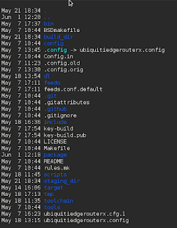
Here is the output directory structure...
....or at least what is written out to MY system when I did the build).

As you can see, I decided to name my configuration with a name that corresponded to the OEM router I used to build the image (handy if you install OpenWRT on multiple OEM routers).
So let's start talking now about why this is confusing.
1. You might expect the toolchain to be in the toolchain directory.
And it is, but it's not. The stuff to build the toolchain is in the toolchain folder....
.
...but the output of the build is not in this directory.
It is probably in the build_dir folder then, right? WRONG.
The build_dir folder is where the build is kicked off from. But once that happens, everything is written out to the staging_dir.
So let's go and take a look at that directory.

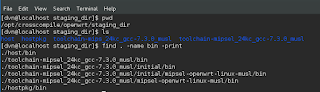
There are a few directories listed, so we will do some investigation and hunt for some binaries. A quick find command shows that indeed, there are some bin directories we can look at.

It turns out that the top level bin directory has the generated executables.
So when OpenWRT builds the toolchain, it writes it into the staging directory for the specific target that was configured in the initial "make menuconfig".
So the next step then, is to make sure that these can be used to build some code on the target device (MIPS32 in our case).
A simple testcompiler.c file is all that is needed:
#include <stdio.h>
int main()
{
printf("Testing MIPS32 Compiler!\n");
}
Next we will set up a simple Makefile to compile this simple source (we could do it on command line of course also).
all: testcompiler.o
testcompiler.o : testcompiler.c
${CC} testcompiler.c -o testcompiler -static -march=mips32
Next, we need to ensure that the proper compiler gets used, and we can do this by using an environment file before we kick off the build with the "make" command.

Now there are a couple of ways to test this binary, but the first and most simple thing to do is to inspect it using the file command, which indeed will confirm whether the binary was built for MIPS32.
Good. It is. So we can now do one of two things:
- Copy it to the target and run it
- Run the binary through an emulator
Emulators can be tricky to install and set up. The one most commonly used for Linux x86_64 architectures is QEMU.
NOTE: I tried to install and use this but got a bunch of errors. So, using QEMU was not as simple as I thought it would be. Something for later.
So, I copied it over to the target and it ran just fine.
Now this process is as simple as it gets. When you get into dependent libraries and packages, building, as well as running, on cross compiled architectures can get quite a bit trickier.
And I do plan to do some more sophisticated cross compiling, so I will write more on that as I do that.
OpenWRT Router (re) Configuration
I had to do some testing today, and I needed two routers to do that testing.
So I decided to use a Ubiquiti EdgeRouterX (MIPS32) for one of the routers, and for the other router I used the same <former> Ubiquiti EdgeRouterX (MIPS32), which I re-imaged with OpenWRT (discussed in previous posts).
Both of these routers enable an L3 switch across all of the ports, by default. And what this means, is that by default, if you plug into any of the ports on the device (except the WAN port of course), you will be on the same default LAN segment.
The Ubiquiti router is a little bit "smarter" in how it is defaulted, and it also has a Wizard that allows you to select how you want your ports set up, at which it will automagically configure the device ports settings for you. You can, for example, select 2 WAN ports (a very advanced link aggregation feature for a router like this), or just a single WAN port (more typical use case). But what this router does, is allow one port (eth0) to be the "admin" port which is on a LAN called 192.168.1.0/24, the WAN port is eth0 (dhcp by default), and the ports eth2, eth3 and eth4 are all on a switch with a LAN numbered 192.168.2.0/24 (or whatever you want it to be, frankly).
The OpenWRT router behaves differently upon default install. It does not have this concept of a dedicated "admin" port on eth0. It assumes (like most routers probably) that eth0 is the WAN port (dhcp by default), and eth1-eth4 are on a L3 switched 192.168.1.0/24 VLAN.
The <potential> issue here, if you use both of these routers together, is that the Ubiquiti knows inherently how to route to that 192.168.1.0/24 admin network that it has set up. So if you pull a 192.168.2.10/24 address via dhcp from the Ubiquiti, and put https://192.168.1.1 in your browser, voila' you get the admin page of the Ubiquiti router (btw....this is also accessible via https://192.168.2.1).
So you have two routers that understand a 192.168.1.0/24 local, separate address space. That's a problem.
I needed to change the OpenWRT router, so that it's address spaces were different than the Ubiquiti router. I thought this would be easy and take 15 seconds, as it does on the Ubiquiti. It was NOT as intuitive. Furthermore, I was very concerned about bricking the router (screw it up such that I could not connect to it or administer it), since I had put OpenWRT on it and wasn't sure what would happen if I paperclip reset it. So I had to be careful, which added even more time.
I managed to pull this off. And in fact, I *did* screw this router up in the process, but was able to reset it with a paperclip, which put the original OpenWRT default configuration back on it (thank goodness).
So here are the steps to create a new subnet on a set of ports:
1. Create a new device
By default, there is a WAN, a WAN6, and a LAN.
NOTE: The WAN6 is confusing and a separate topic to discuss. I deleted this WAN6 thinking it was redundant, and this is probably one of the reasons I had to reset the router.
I created a new LAN2 interface as a first step.

Now you can do this manually, if you want to play with fire, and ssh into the device and edit the file /etc/config/network. The setting for that in the file would look like this:
config interface 'lan2'
option type 'bridge'
option proto 'static'
option ifname 'eth0.3'
option ipaddr '192.168.3.1'
option netmask '255.255.255.0'
But if you edit these files "hot" while the device is running and happen to make any kind of typo or syntax error, and you might find yourself with some big problems and unable to log into the device.
So I decided to use the GUI, because would assume a GUI knows how to save things properly (if not this router is in some big trouble).
If you click on "Edit", you will see some of the fields that I had to examine, and some of which I had to fill out to make sure this device was created properly.
The first tab is the "General Setup" tab.
 Let's discuss what is important here.
You will notice that the IP address and network mask is filled out. This essentially "sets" the subnet for that interface. DHCP will use this network automatically.
I found this very confusing and this is very different from how Ubiquiti and other routers establish the network for an interface.
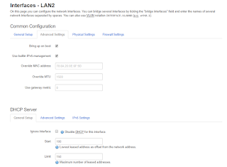
First, there is the "Advanced" tab. I will show that here. I made no changes to this tab.
By the way....the DHCP Server section below shows up across all tabs, which in my opinion is a bit of a design flaw (why not make it its own tab?).
There are some fields related to the DHCP server, and one might be interested in changing the default lease time or making other changes in the "advanced" field. I chose to stick with all of the defaults here.
 Then there is the "Physical" tab. The first decision is to name your interface not in use.
We will go with eth0.3 which, as the GUI demonstrates, suggests that each "dot x" relates to a logical VLAN off of the L3 switch, which is named (or mapped to) eth0.
The other important decision is whether you want to add that interface to a bridge. I elected to do so, since the first default interface LAN is on a bridge (I did it for consistency).
NOTE: It is worth pointing out that you indeed can add multiple interfaces to a single bridge. But I don't suggest doing this unless you know precisely why you are doing it.
So for now, each Interface is on its own dedicated bridge. There is a 1:1 relationship between Interface and Bridge.
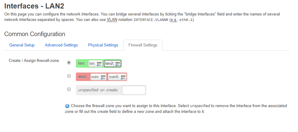
Next, there is a tab called "Firewall Settings". Let's examine that.
 The OpenWRT router uses the well-known and common concept of "zones of security". By default there is a WAN zone, and a LAN zone. The WAN zone has policies and rules concerning traffic that is entering (ingress) or leaving (egress) the WAN port. The LAN zone has policies and rules for traffic that are internal to the router (between VLANs or otherwise L3-Switched Traffic).
You have the ability to define a new zone (LAN2), and put your new LAN2 interface in a LAN2 zone (and this would be a good idea of you needed special rules for this interface that differed between LAN2 and LAN). But setting up zones with rules takes time, and can be error-prone. Plus we don't have any specific reason to believe that our LAN2 interface needs anything different than the other LAN interface from a security point of view.
So we will share the same firewall zone for both the LAN and L2 interfaces. For now.
Are we done? NO. There is more work to do. Quite a bit actually.
Let's stop for a moment and review what we have done and where we are.


So I decided to use a Ubiquiti EdgeRouterX (MIPS32) for one of the routers, and for the other router I used the same <former> Ubiquiti EdgeRouterX (MIPS32), which I re-imaged with OpenWRT (discussed in previous posts).
Both of these routers enable an L3 switch across all of the ports, by default. And what this means, is that by default, if you plug into any of the ports on the device (except the WAN port of course), you will be on the same default LAN segment.
The Ubiquiti router is a little bit "smarter" in how it is defaulted, and it also has a Wizard that allows you to select how you want your ports set up, at which it will automagically configure the device ports settings for you. You can, for example, select 2 WAN ports (a very advanced link aggregation feature for a router like this), or just a single WAN port (more typical use case). But what this router does, is allow one port (eth0) to be the "admin" port which is on a LAN called 192.168.1.0/24, the WAN port is eth0 (dhcp by default), and the ports eth2, eth3 and eth4 are all on a switch with a LAN numbered 192.168.2.0/24 (or whatever you want it to be, frankly).
The OpenWRT router behaves differently upon default install. It does not have this concept of a dedicated "admin" port on eth0. It assumes (like most routers probably) that eth0 is the WAN port (dhcp by default), and eth1-eth4 are on a L3 switched 192.168.1.0/24 VLAN.
The <potential> issue here, if you use both of these routers together, is that the Ubiquiti knows inherently how to route to that 192.168.1.0/24 admin network that it has set up. So if you pull a 192.168.2.10/24 address via dhcp from the Ubiquiti, and put https://192.168.1.1 in your browser, voila' you get the admin page of the Ubiquiti router (btw....this is also accessible via https://192.168.2.1).
So you have two routers that understand a 192.168.1.0/24 local, separate address space. That's a problem.
I needed to change the OpenWRT router, so that it's address spaces were different than the Ubiquiti router. I thought this would be easy and take 15 seconds, as it does on the Ubiquiti. It was NOT as intuitive. Furthermore, I was very concerned about bricking the router (screw it up such that I could not connect to it or administer it), since I had put OpenWRT on it and wasn't sure what would happen if I paperclip reset it. So I had to be careful, which added even more time.
I managed to pull this off. And in fact, I *did* screw this router up in the process, but was able to reset it with a paperclip, which put the original OpenWRT default configuration back on it (thank goodness).
So here are the steps to create a new subnet on a set of ports:
1. Create a new device
By default, there is a WAN, a WAN6, and a LAN.
NOTE: The WAN6 is confusing and a separate topic to discuss. I deleted this WAN6 thinking it was redundant, and this is probably one of the reasons I had to reset the router.
I created a new LAN2 interface as a first step.

Now you can do this manually, if you want to play with fire, and ssh into the device and edit the file /etc/config/network. The setting for that in the file would look like this:
config interface 'lan2'
option type 'bridge'
option proto 'static'
option ifname 'eth0.3'
option ipaddr '192.168.3.1'
option netmask '255.255.255.0'
But if you edit these files "hot" while the device is running and happen to make any kind of typo or syntax error, and you might find yourself with some big problems and unable to log into the device.
So I decided to use the GUI, because would assume a GUI knows how to save things properly (if not this router is in some big trouble).
If you click on "Edit", you will see some of the fields that I had to examine, and some of which I had to fill out to make sure this device was created properly.
The first tab is the "General Setup" tab.

You will notice that the IP address and network mask is filled out. This essentially "sets" the subnet for that interface. DHCP will use this network automatically.
I found this very confusing and this is very different from how Ubiquiti and other routers establish the network for an interface.

First, there is the "Advanced" tab. I will show that here. I made no changes to this tab.
By the way....the DHCP Server section below shows up across all tabs, which in my opinion is a bit of a design flaw (why not make it its own tab?).
There are some fields related to the DHCP server, and one might be interested in changing the default lease time or making other changes in the "advanced" field. I chose to stick with all of the defaults here.

We will go with eth0.3 which, as the GUI demonstrates, suggests that each "dot x" relates to a logical VLAN off of the L3 switch, which is named (or mapped to) eth0.
The other important decision is whether you want to add that interface to a bridge. I elected to do so, since the first default interface LAN is on a bridge (I did it for consistency).
NOTE: It is worth pointing out that you indeed can add multiple interfaces to a single bridge. But I don't suggest doing this unless you know precisely why you are doing it.
So for now, each Interface is on its own dedicated bridge. There is a 1:1 relationship between Interface and Bridge.
Next, there is a tab called "Firewall Settings". Let's examine that.
You have the ability to define a new zone (LAN2), and put your new LAN2 interface in a LAN2 zone (and this would be a good idea of you needed special rules for this interface that differed between LAN2 and LAN). But setting up zones with rules takes time, and can be error-prone. Plus we don't have any specific reason to believe that our LAN2 interface needs anything different than the other LAN interface from a security point of view.
So we will share the same firewall zone for both the LAN and L2 interfaces. For now.
Are we done? NO. There is more work to do. Quite a bit actually.
Let's stop for a moment and review what we have done and where we are.
- We have created a new Interface
- We have named it and put it on a bridge
- We have put it in a firewall zone.
So why would this not be enough to put the interface into use?
Because we do not know what ports will use this interface!
Right now, the ports are all bound to the L3 Switch, and the switch is set up to use a single VLAN which has 192.168.x.0/24 with a gateway address of 192.168.x.1 (x = 1 in a default configuration of OpenWRT).
So we now need to go into the Network / Switch menu at the very top of the administrative interface.

By default, there will only be two rows here.
- VLAN ID 1 (LAN)
- VLAN ID 2 (WAN)
Let's discuss these two default VLANs.
VLAN ID of 1 is essentially mapped to the LAN. The smoking gun indicator of this is that ports LAN1-4 are not set to "off". They are therefore in use, but set to "untagged" (don't assume untagged means unused - a very common misconception).
VLAN ID of 2 is essentially mapped to the WAN because it has the inversion situation where the ports LAN1-4 are set to off (not in use), but the WAN port is set to "untagged" (again, in use but untagged).
Both these ports interface with the CPU port (switch port) eth0, which can be viewed perhaps analogous to bus for traffic. The Bus tags traffic so that it knows what VLAN the traffic is coming from or going to.
We need to add a VLAN ID of 3 for our new bridged interface LAN 2 we created. And we are going to change the port assignments so that 2 ports are on the LAN, and 2 ports are on LAN2. Once this is done, each of these Interfaces can have an address space (e.g. 192.168.2.0/24 and 192.168.3.0/24).
NOTE: if we wanted to, we could create 3 new interfaces and 3 new VLAN IDs so that the router could manage 4 subnets. But we don't need 4 subnets. We only need two. So we are only going to "stripe" the router with a 2 x 2 configuration (two ports subnet=A, and two ports subnet=B). And when we do that we will see this screen below.

As we can see, VLAN ID of 1 has the LAN 1 and LAN 2 ports set to "untagged", and LAN 3 and LAN 4 ports are turned (set to) off.
VLAN ID 2 has LAN 3 and LAN 4 ports set to untagged, and LAN 1 and LAN 2 ports set to off.
There are some very bad GUI design issues here on the Switch interface, and let's discuss those:
The fact that the switch uses the labels LAN 1, LAN 2, LAN 3 and LAN 4 is confusing.
- There is a LAN 1 interface
- There is a LAN 2 interface we just created
Thank goodness they have pictures of the ports here, or people could really screw this router up.
From here, we could be finished. We could plug devices into the ports and ensure you get the right IP addresses on each port (e.g. 192.168.2.x on ports 1 and 2 and 192.168.3.x on ports 3 and 4).
I will avoid a discussion on DHCP and DNS, but there is a tab at the top of the administrative interface for DHCP/DNS, and you can configure all of the typical things in a series of tabs on that menu item.
The one thing that may be worth mentioning is the "Static Leases" section which is a fixture at the bottom of the "DHCP/DNS" page no matter what tab you happen to be working with.
On this page, you can set mac address IP reservations. And one thing I did not like about this is that it doesn't seem to prevent you from putting the wrong subnet into the reservation. So if the port is a 192.168.2.0/24 port, you can still put in a 192.168.3.0/24 IP for that mac. The GUI does not care or validate or otherwise govern the assignments. So you better know what network the port is on before you start entering reservations in the GUI. And this could be a pain if you had 4 subnets and a ton of reservations to type in here.
Okay. That is all. As we can see, this router is not as "nimble" to administer as the Ubiquiti EdgeRouterX.
Router Hack: VPN Filter
This is a good article that explains the VPN Filter hack.
https://arstechnica.com/information-technology/2018/05/hackers-infect-500000-consumer-routers-all-over-the-world-with-malware/

Building a Cross Compilation Toolchain for MIPS32 - Part II
I spent about 3 days trying to get the cross compilation toolchain for MIPS 32 working. Maybe this wasn't enough time, but it was all of the time I had before I had to stick a knife in the effort and call it done - unsuccessfully.
Compiling the toolchain is essentially done in 3 steps:
1. Compile binutils for the target architecture
2. Compile a lightweight C compiler for the target architecture
3. Compile a standard C Library (e.g. glibc) for the target architecture using the compiler from step 2.
I could never make this work. I could usually get #1 to work. I could usually get #2 to work. I could never get #3 to work.
At this point, I went back and reverse-engineered the toolchain that OpenWRT was using for MIPS32. The CMakefiles, scripts, and generated Makefiles were extremely complex. And I saw patches being used in several places. Patches to scripts. Patches to Makefiles. Patches to header files.
At that point, I decided I didn't have the time or bandwidth to complete the project of building a cross-compilation toolchain successfully.
I decided instead to try and use the one from OpenWRT that was already built. More on that in a subsequent post.
Building a Cross Compilation Toolchain for MIPS32 - Part I
It seems there are a lot of people out there who do cross-compiling for the ARM processor (i.e. Raspberry Pi uses an ARM if I'm not mistaken).
But there aren't many people out there that have done this for a MIPS32 processor.
I noticed that when I built OpenWRT and used the make menuconfig utility to specify the target parameters, it has its own cross-compilation framework and engine in it.
To compile some ADDITIONAL software of your own, you would need to reverse-engineer (and possible recycle and reuse) this framework. Or, you could look into building your own cross-compilation platform.
I looked into the former, and then did some quick web searches to attempt the latter.
In doing the web searches, I began to learn the "methodology" for doing cross compilation in general. The steps seem more or less the same, no matter what kind of platform you are compiling for. It involves building a "toolchain". A Toolchain is essentially defined as "the tools used for cross compilation".
I found a guy who built such a toolchain for MIPS, and began the process using his site as a guide:
http://www.lara.prd.fr/users/oliviermehani/2007ie/mipsellinuxtoolchain
I like the fact that he lays out the process (or, at least, HIS process):
a) Download and Build binutils
b) Download and build gcc
c) Download and build gcc-lib
Another link I came across reaffirmed these steps, but with some additional insight and information.
http://cowlark.com/2009-07-04-building-gcc/
In this link, he explains, for example, why it is important to do your builds from a different directory than where the source is initially downloaded and extracted/spooled.
BTW...in his article he suggests building binutils from an outside directory but the first link does not do this. I was following the first set of steps from Olivier Mehani before I came across this additional link.
So What Went Wrong Initially
I was following the instructions on Oliver Mehani's site "to the letter". Which means that I decided to use the same versions of binutils, gcc and gcclib that he used in the article.
I failed to realize how old these versions were - some of which were going back to 2004 (it is now 2018). I also failed to realize that the true target, which is OpenWRT running on a former Ubiquity EdgeRouterX device, is a MUCH MUCH newer device and Linux operating system.
In fact, the OS is now called LEDE rather than OpenWRT (OpenWRT split with LEDE and the two have just recently merged back into a single entity and they now use the term LEDE for the OS).
When I downloaded the 2.14 version of binutils, it configured and built (and installed) just fine.
Building gcc also went fine although time consuming (at least on a single or dual core Virtual Machine on VirtualBox running on a Windows 10 laptop).
When I compiled gcclib, I got an error about it being incompatible with the binutils version I was using.
At this point, I began trying some different versions of both binutils as well as the compiler. I first downloaded the most recent versions of these. And got a series of nasty errors on the compile and make processes of gcc.
Later the light bulb went off and I realized that the best practice would be to use the same versions of binutils, gcc and gcclib that were on the target device (again, OpenWRT MIPS32 image I installed on the Ubiquity EdgeRouterX device).
So the versions on that device are:
GCC Prequisite Dependencies
When I compiled the original 2.13 of binutils and then compiled the 3.3.4 version of gcc on Olivier's page, binutils compiled fine but the gcc produced an error (a data type I believe it was).
So this led to me trying new versions and combinations/permutations of binutils and gcc trying to find a magic combination that would work (configure, make and make install).
Later more recent versions of gcc started to complain about some extraneous packages that it cold not find, telling me I could specify these libraries as compiler options:
configure: error: Building GCC requires GMP 4.2+, MPFR 2.4.0+ and MPC 0.8.0+. Try the --with-gmp, --with-mpfr and.or --with/mpc options to specify their locations.
I did not get these errors on gcc 3.3.4, so I started to get frustrated about the circuitous loop of package dependencies and considered abandoning my effort.
But - via a web search , I learned that that in version 5.4.0 of gcc, a script was packaged in the /contrib directory called "download_prerequisites" and the rather sophisticated script (I did not study it) downloads and positions these packages so that they can be built and incorporated into gcc seamlessly.
NOTE: I noticed this script was NOT included in version 4.3.3 of gcc, which I later used, but I found that I could port the script from version 5.4.0 to 4.3.3 and it appeared to work.
GCC Version
After initially trying to get 3.3.4 to work, I downloaded version 5.4.0 of the gcc compiler and after pulling down the threads and running the pre-req script to install GMP, MPFR and MPC, I tried to run the configure script which bailed with the error:
"@itemx must follow @item"
TexInfo Error on GCC Configure
Some web searches showed that the issue was the version of texinfo (I was using a recent 5.x version of it on my CentOS7 Linux VM). I downloaded the tool rpmreaper to see if it was safe to uninstall it (it was), and installed a much earlier version of texinfo (4.13) that someone on the web suggested might be valid to use in order to avoid this error. I compiled it and installed it, and tried to run the configure script again on version 5.4.0 of gcc.
The "configure" script in gcc is a VERY long script indeed to run (>30 min) on my laptop. You cannot specify -j X with the configure script, so it is serial, much like a linking process.
Link tests are not allowed after GCC_NO_EXECUTABLES
Finally - after waiting for what seemed like the better part of an hour, the configure process on gcc 5.4.0 bailed out with the following error:
checking dynamic linker characteristics... configure: error: Link tests are not allowed after GCC_NO_EXECUTABLES.
Web searches appear inconclusive, although I do see some people complaining about this issue. Most of the people on these threads suggest that an earlier version of gcc may fix the issue.
So - we will attempt version 4.3.3 of the gcc compiler, which someone on the web suggests may work. First we will do a rm -rf on the gcc-build directory, then download this version 4.3.3 and re-run our configure script again to see if it solves this issue.
Version 4.3.3 of gcc
And off we go. Again. Actually, the configure script on this came back lickety split.
So now we will run, from our gcc-build directory, the "make -j 2" command to try and leverage two cores that we have provisioned on this virtual machine.
And off we go. Again. Waiting. Again.
But there aren't many people out there that have done this for a MIPS32 processor.
I noticed that when I built OpenWRT and used the make menuconfig utility to specify the target parameters, it has its own cross-compilation framework and engine in it.
To compile some ADDITIONAL software of your own, you would need to reverse-engineer (and possible recycle and reuse) this framework. Or, you could look into building your own cross-compilation platform.
I looked into the former, and then did some quick web searches to attempt the latter.
In doing the web searches, I began to learn the "methodology" for doing cross compilation in general. The steps seem more or less the same, no matter what kind of platform you are compiling for. It involves building a "toolchain". A Toolchain is essentially defined as "the tools used for cross compilation".
I found a guy who built such a toolchain for MIPS, and began the process using his site as a guide:
http://www.lara.prd.fr/users/oliviermehani/2007ie/mipsellinuxtoolchain
I like the fact that he lays out the process (or, at least, HIS process):
a) Download and Build binutils
b) Download and build gcc
c) Download and build gcc-lib
Another link I came across reaffirmed these steps, but with some additional insight and information.
http://cowlark.com/2009-07-04-building-gcc/
In this link, he explains, for example, why it is important to do your builds from a different directory than where the source is initially downloaded and extracted/spooled.
BTW...in his article he suggests building binutils from an outside directory but the first link does not do this. I was following the first set of steps from Olivier Mehani before I came across this additional link.
So What Went Wrong Initially
I was following the instructions on Oliver Mehani's site "to the letter". Which means that I decided to use the same versions of binutils, gcc and gcclib that he used in the article.
I failed to realize how old these versions were - some of which were going back to 2004 (it is now 2018). I also failed to realize that the true target, which is OpenWRT running on a former Ubiquity EdgeRouterX device, is a MUCH MUCH newer device and Linux operating system.
In fact, the OS is now called LEDE rather than OpenWRT (OpenWRT split with LEDE and the two have just recently merged back into a single entity and they now use the term LEDE for the OS).
When I downloaded the 2.14 version of binutils, it configured and built (and installed) just fine.
Building gcc also went fine although time consuming (at least on a single or dual core Virtual Machine on VirtualBox running on a Windows 10 laptop).
When I compiled gcclib, I got an error about it being incompatible with the binutils version I was using.
At this point, I began trying some different versions of both binutils as well as the compiler. I first downloaded the most recent versions of these. And got a series of nasty errors on the compile and make processes of gcc.
Later the light bulb went off and I realized that the best practice would be to use the same versions of binutils, gcc and gcclib that were on the target device (again, OpenWRT MIPS32 image I installed on the Ubiquity EdgeRouterX device).
So the versions on that device are:
- binutils v2.27
- gcc v5.4.1
- glibc v5.4.1
The closest ones I could find on the mirrors were:
- binutils v2.27
- gcc v5.4.0
- glibc v5.4.0
GCC Prequisite Dependencies
When I compiled the original 2.13 of binutils and then compiled the 3.3.4 version of gcc on Olivier's page, binutils compiled fine but the gcc produced an error (a data type I believe it was).
So this led to me trying new versions and combinations/permutations of binutils and gcc trying to find a magic combination that would work (configure, make and make install).
Later more recent versions of gcc started to complain about some extraneous packages that it cold not find, telling me I could specify these libraries as compiler options:
configure: error: Building GCC requires GMP 4.2+, MPFR 2.4.0+ and MPC 0.8.0+. Try the --with-gmp, --with-mpfr and.or --with/mpc options to specify their locations.
I did not get these errors on gcc 3.3.4, so I started to get frustrated about the circuitous loop of package dependencies and considered abandoning my effort.
But - via a web search , I learned that that in version 5.4.0 of gcc, a script was packaged in the /contrib directory called "download_prerequisites" and the rather sophisticated script (I did not study it) downloads and positions these packages so that they can be built and incorporated into gcc seamlessly.
NOTE: I noticed this script was NOT included in version 4.3.3 of gcc, which I later used, but I found that I could port the script from version 5.4.0 to 4.3.3 and it appeared to work.
GCC Version
After initially trying to get 3.3.4 to work, I downloaded version 5.4.0 of the gcc compiler and after pulling down the threads and running the pre-req script to install GMP, MPFR and MPC, I tried to run the configure script which bailed with the error:
"@itemx must follow @item"
TexInfo Error on GCC Configure
Some web searches showed that the issue was the version of texinfo (I was using a recent 5.x version of it on my CentOS7 Linux VM). I downloaded the tool rpmreaper to see if it was safe to uninstall it (it was), and installed a much earlier version of texinfo (4.13) that someone on the web suggested might be valid to use in order to avoid this error. I compiled it and installed it, and tried to run the configure script again on version 5.4.0 of gcc.
The "configure" script in gcc is a VERY long script indeed to run (>30 min) on my laptop. You cannot specify -j X with the configure script, so it is serial, much like a linking process.
Link tests are not allowed after GCC_NO_EXECUTABLES
Finally - after waiting for what seemed like the better part of an hour, the configure process on gcc 5.4.0 bailed out with the following error:
checking dynamic linker characteristics... configure: error: Link tests are not allowed after GCC_NO_EXECUTABLES.
Web searches appear inconclusive, although I do see some people complaining about this issue. Most of the people on these threads suggest that an earlier version of gcc may fix the issue.
So - we will attempt version 4.3.3 of the gcc compiler, which someone on the web suggests may work. First we will do a rm -rf on the gcc-build directory, then download this version 4.3.3 and re-run our configure script again to see if it solves this issue.
Version 4.3.3 of gcc
And off we go. Again. Actually, the configure script on this came back lickety split.
So now we will run, from our gcc-build directory, the "make -j 2" command to try and leverage two cores that we have provisioned on this virtual machine.
And off we go. Again. Waiting. Again.
Thursday, May 10, 2018
OpenWRT on a Ubiquiti EdgeRouterX - Part II
So in Part I, I built the source from scratch and generated an image that I could load onto a Ubiquiti EdgeRouterX device.
This worked - in the sense that I was able to boot that image and get a functional and working OpenWRT (LEDE) image.
The router handed me an IP address like it should have. The router was passing my packets out to the web and back, performing its SNAT functions like a good little router should.
The problems started when I tried to use the package manager.
The first problem I ran into using the package manager was the fact that the urls in the feeds.conf file were not resolving. They were all using openwrt.git.org. This may have been because the git sites for openwrt were down (temporarily). I fixed these urls by looking out on the web for the actual github urls, and commenting out the git.org sites and using the github sites instead.
Once I fixed this issue, I noticed that I kept getting an error from the opkg utility about having zero bytes in the overlay file system.
In looking, I did not have an /overlay file system. I had a directory off the root directory called /overlay.
In doing a google search on this issue I found a number of forum posts but when you clicked them, they links timed out.
Clearly, something went wrong when I built the image.
I typed the mount command, and saw a / mounted on a rootfs file system. I saw a tmpfs on /tmp. But no overlay. I didn't really understand the overlay file system anyway, so I was in trouble there. I knew enough to believe I might be able to manually mount this file system on a device, but I didn't see the device and things looked quite intimidating.
I began to realize that I was quite screwed. I had a router that I could not administratively update or manage because the file system was not "correct". I considered paper clipping (hard reset) the router, but I wasn't sure what that would do since I had replaced the original flash image from Ubiquiti with the one from OpenWRT. It seemed risky to do that.
I finally found a page that allowed me to take a more sensible risk. I found a page that had hardware / firmware images, and I decided to "upgrade" my router with the new image listed on this page. I wasn't sure if that would actually fix the file system layout on the flash or not, and I suspected it wouldn't, but I gave it a try nonetheless.
So after downloading the new flash image, I discovered another issue. This image I had built did not include the Luci GUI, so I needed to do anything and everything via command line. I found a way to upgrade the router via command line with this link:
https://openwrt.org/docs/guide-user/installation/sysupgrade.cli
Using ssh, I copied the downloaded image into a temporary directory and ran the command:
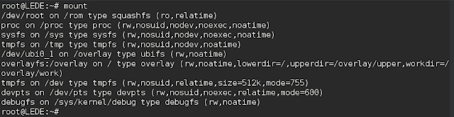
Now we have a /dev/root on /rom of type squashfs - something we did not see before.
Most importantly, we see the overlayfs mounted on the / folder in a directory called /overlay.
And some others we did not see before, either.
Things look better. We can launch a GUI and we can update our packages now. I installed OpenVPN, for example, which added itself to the "Services" menu.
This worked - in the sense that I was able to boot that image and get a functional and working OpenWRT (LEDE) image.
The router handed me an IP address like it should have. The router was passing my packets out to the web and back, performing its SNAT functions like a good little router should.
The problems started when I tried to use the package manager.
The first problem I ran into using the package manager was the fact that the urls in the feeds.conf file were not resolving. They were all using openwrt.git.org. This may have been because the git sites for openwrt were down (temporarily). I fixed these urls by looking out on the web for the actual github urls, and commenting out the git.org sites and using the github sites instead.
Once I fixed this issue, I noticed that I kept getting an error from the opkg utility about having zero bytes in the overlay file system.
In looking, I did not have an /overlay file system. I had a directory off the root directory called /overlay.
In doing a google search on this issue I found a number of forum posts but when you clicked them, they links timed out.
Clearly, something went wrong when I built the image.
I typed the mount command, and saw a / mounted on a rootfs file system. I saw a tmpfs on /tmp. But no overlay. I didn't really understand the overlay file system anyway, so I was in trouble there. I knew enough to believe I might be able to manually mount this file system on a device, but I didn't see the device and things looked quite intimidating.
I began to realize that I was quite screwed. I had a router that I could not administratively update or manage because the file system was not "correct". I considered paper clipping (hard reset) the router, but I wasn't sure what that would do since I had replaced the original flash image from Ubiquiti with the one from OpenWRT. It seemed risky to do that.
I finally found a page that allowed me to take a more sensible risk. I found a page that had hardware / firmware images, and I decided to "upgrade" my router with the new image listed on this page. I wasn't sure if that would actually fix the file system layout on the flash or not, and I suspected it wouldn't, but I gave it a try nonetheless.
So after downloading the new flash image, I discovered another issue. This image I had built did not include the Luci GUI, so I needed to do anything and everything via command line. I found a way to upgrade the router via command line with this link:
https://openwrt.org/docs/guide-user/installation/sysupgrade.cli
Using ssh, I copied the downloaded image into a temporary directory and ran the command:
sysupgrade -v /tmp/*.binAnd - lo and behold - after rebooting, I got a new, much superior image and experience. I had the Luci GUI. The file system looked proper.
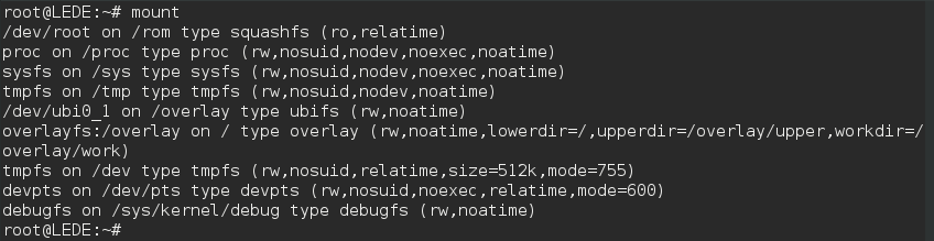
Now we have a /dev/root on /rom of type squashfs - something we did not see before.
Most importantly, we see the overlayfs mounted on the / folder in a directory called /overlay.
And some others we did not see before, either.
Things look better. We can launch a GUI and we can update our packages now. I installed OpenVPN, for example, which added itself to the "Services" menu.
Tuesday, May 8, 2018
OpenWRT on a Ubiquity EdgeRouterX - Part I
We have been using these Ubiquity EdgeRouter X devices for a while now in here (about a year). They're incredible devices; can't say enough about them.
We were curious to see if you could run OpenWRT on these.
The first thing we had to do is to get some intelligence on the device.
We could have cracked open the case and studied the circuit board, but we didn't do that. By using search engines, we were able to ascertain that it was a 32 bit MIPS processor (MIPS Technologies); MIPS32 1004K. They make a couple of renditions of these chips (i.e. MIPS321004Kc or MIPS321003Kf), the c standing for "coherent" and the f standing for "floating point".
After logging onto the device and looking in /proc/cpuinfo (issuing the command "show hardware cpu" also shows this information), we were able to ascertain that the board (system type?) is MediaTek MT6721 ver:1 eco:3. The processor was confirmed as MIPS 1004Kc V2.15.
So the next step was to figure out how to download and compile OpenWRT on this chipset. This can get hairy and complicated, depending on how much support for the chip there is out in the communities.
As it turns out, if you download OpenWRT on a Linux machine, there is some built-in cross compilation support for MIPS32 right within OpenWRT itself. Apparently the gnu compiler gcc supports the MIPS32 target architecture also, which is nice [ NOTE: validate this ].
If there wasn't, you would need to try to find a toolchain (which has compiler, linker and so forth), and [try to] build OpenWRT from scratch, and this would also include building any and all libraries that the code referenced - a potentially huge job. Just doing the Makefiles could take a week or two.
So to compile it, you need to download the OpenWRT source code (I created a directory called /opt/crosscompile and untarred to that, which creates a openwrt directory) and from the top level directory run "make config", or, in my case, I ran "make menuconfig". Running menuconfig pulls up a curses-based menu that allows you to configure your build - including the options to include in your OpenWRT and target platform specifics for a cross-compile.
Build Options
Originally when I ran this, I went to select the Target System and chose "MIPS Malta CoreLV board (qemu)". There was also an option called "MIPS pistachio". I was confused as to which was the right one. And - YOU BETTER CHOOSE THE RIGHT ONE! If you don't, you can risk bricking (ruining) the device when you try to run the code.
It turns out, that neither is the right one. The correct choice for "Target System" was further down below, called "MediaTek Ralink MIPS" (other than the Mediatek and MIPS, there wouldn't be any easy way to figure this out).
The Subtarget is MT6721, which now starts to make some sense based on the output of what showed up in /proc/cpuinfo on the Ubiquity device. But this subtarget would never have shown up as an option if you didn't get the proper Target System right to begin with.
If you select the proper Target and Subtarget, you get an option for "Ubiquity EdgeRouter X" as the Target Profile.
And finally, for "Target Image", you need to make sure that "ramdisk" is selected because this generates a "img" file that is tarred into a tarball that you will eventually boot into the Ubiquity image loader to boot the OpenWRT image you compile.
I made no changes to the Global Build Settings. Initially, I did select "Build the OpenWRT Image Builder" and "Build the OpenWRT SDK" options in the make menuconfig menu listing, but I had to back these out because the compile was spewing out warnings about library dependencies.
Libraries
Running the build without fully reading the README is almost always a mistake, and it bit me here as well. There is a script called "feeds" that will update and install the dependent libraries. This needs to be run.
This script failed when I ran it, and this COULD be because OpenWRT had an issue with their Github site that day (the mirrors).
I went on the web and did some checking, and the packages I needed in the build seemed to be on https://github.com/XXXXX as opposed to https://openwrt.git.org which is what the scripts were all primed with. So what I did was to fix these urls one at a time, and iteratively kick off the build until it launched with no dependent library warnings.
Build
After the build completed (which took a while - about 2 hours - in a 2 core VirtualBox virtual machine running CentOS7 Linux), I had to figure out where the resultant images were written. They are actually written to the /openwrt/bin/targets folder. The full path is:
/opt/crosscompile/openwrt/bin/targets/ramips/mt7621/openwrt-ramips-mt7621-ubnt-erx-initramfs-factory.tar.
There is also a bin file in this directory as well, but it is the tar you need to load into the device.
Transfer
The next step is secure copy (scp) the tar file into a temporary directory on the Ubiquity EdgeRouterX device. We elected to put it into /tmp.
Then - once copied over, you can log into the UbiquityEdgeRouterX via ssh or through the web console, and go into the temporary directory and type:
"add system image openwrt-ramips-mt7621-ubnt-erx-initramfs-factory.tar"
If this add system command worked you should get a confirmation (i.e. image added). It will place the image on a list of images stored on the device, and mark that image as bootable (apparently it works much like a LIFO queue, where the last image added is the bootable one).
It is now time to reboot the device, by typing "reboot". This is the moment of truth.
But...there is an important step!
Change Ethernet Cable to eth1 on the device!!!!
On the Ubiquity device, eth0 is the management interface, and eth1 is actually the WAN link (eth2-4 are local links).
On OpenWRT, it uses eth0 as a WAN link, and eth1 is the management link.
If you attempt to reboot the device and your cable is [ still ] plugged into the wrong NIC, you will not be able to log in and access the device under OpenWRT.
So switching the cable from eth0 to eth1 is the next step...
Image Re-load
If there any major issues with the image I think adding the image would have flagged that. But the real proof is when you reboot the device.
In our case, the image booted with a "OpenWRT" ASCII MOTD banner, letting you know it booted.
Explore
From here, you can dance around the OpenWRT file systems to your hearts content, as this review stops here.
The only thing I will mention is that I did install the graphical menu for OpenWRT, called Luci.
I will log into that web interface to see what it looks like as I explore OpenWRT.
Thursday, April 26, 2018
SDN Solutions
Note to self: Look into Aryaka Networks
I am told they have a very robust and mature orchestration solution.
Look into Thousand Eyes
Not sure what this is all about.
TCPKali Part II
I've spent about a week testing with this tcpkali tool now.
This is the test case I initially put together, which is to test connections between two CentOS 7 VMs via an Ubuntu VM (IP Forwarder / Router).

The tool spawns worker threads that test connection establishment and bandwidth on each of the connections, both based on an individual thread and collectively.
One thing I did run into with using Lighttpd, is that at high volume levels I kept getting invalid request headers. I wasn't sure if this was tcpkali messing up the headers, or if it was Lighttpd.
So I switched the architecture a bit (based on the suggestion of one of the other engineers in here). Instead of using Lighttd as the web server, I put tcpkali on both sides (left and right) - in client and server mode respectively.

This worked much better than using Lighttpd as a web server. You can send messages and run the server in active or silent mode, returning responses or discarding them.
The tcpkali has some great features. One HUGE feature is the ability to send requests per second with the -r option. The tool attempts to ramp up to the specified number of connections, and if it cannot do this, it will bail without examining throughput measurements. I did notice that it sends data with the -r option DURING the ramp-up period, in addition to after. The tool also has other features like the connect rate, so that if you are establishing 100K connections you can speed up that process by doing 10K or 20K a clip rather than smaller default limits.
What I discovered in the testing I was doing, was that the connection rate had a profound effect on the number of connections you could establish. The default connection rate is 100. And this works fine for up to about 10,000 connections. But if you try to go to higher than that, the rate starts to inhibit your ability to scale the connections and you need to tweak it higher - just not too much higher.
The sweet spot I discovered was a 1,000 : 1 ratio. So 10,000 connections would use a rate of 100 connections per second, 20,000 would use a rate of 200 connections per second, and so forth.
Thursday, April 12, 2018
TCPKali
Today the QA team told me they had selected a tool called TCPKali (but weren't wed to it). They wanted me to download it, compile it, and try it out, as they thought they would use this to test connection scaling from clients running our product.
So I did this yesterday evening. It requires a number of kernel parameters to be changed so you can actually scale. This took me down a deep road of TCP State Transition and TIME WAIT. Rather than just blindly change kernel parameters, I read a couple of good articles on this:
http://developerweb.net/viewtopic.php?id=2941
http://www.serverframework.com/asynchronousevents/2011/01/time-wait-and-its-design-implications-for-protocols-and-scalable-servers.html
Okay...now I know why I am changing the reuse and recycle parms on TIME WAIT.
I actuallly tested this by setting up a Lighttpd web server and using the man page examples. I was thinking Lighttpd would be closing the socket connections down and going into TIME WAIT state but in my testing I saw that the client (TCPKali) was actually racking up sockets in this state until I set those kernel parms which kept that number down to a lower number.
Libnet and Libpcap
In the Jon Erickson book, he discusses the differences between libnet and libpcap.
Libnet is used to send packets (it doesn't receive).
Libpcap is used to filter (receive) packets - it doesn't send.
So you need both modes to have, well, "a full duplex solution".
I downloaded and compiled a bunch of libnet code examples so I can fiddle around and send packets under different example scenarios. It's fairly easy to use, I think. All in C language.
Libpcap is a library that allows you to initialize a listener that goes into a loop, and you can pass in a BPF (Berkeley Packet Filter) and a Callback function that can handle packets that are fed into the callback function based on the filter criteria.
I had issues running the libpcap on VirtualBox virtual machines that had a bridged interface to the host. I need to re-run the code from the libpcap tutorial I was doing on a dedicated Linux box, or maybe change the adaptor type on the Virtual Box VMs.
Security and Hacking - Part I
I don't usually write much about Security and Hacking, but I will need to do a little bit of that because that is what I have been working on lately.
I went to the RSA show a couple years ago and that bootstrapped my involvement in security. The Dispersive DVN, after all, is all about Security. We have had a number of people come in and Pen Test the networks, and I have read those reports. Recently, as part of Research, once I finished Orchestration, they asked me if I would bolster my skills in this area and do some internal pen testing of our network. This is a big undertaking, to say the least.
I started with a book called Hacking (2nd Edition), The Art of Exploitation, by Jon Erickson. This book is not for the script kiddies. It uses practical Assembler and C examples on a (dated) version of Ubuntu that you compile and run as part of going through the book. I have gone through the entire book, page by page. I've learned some very interesting things from this book. Where I kind of got lost was in the ShellCode sections - which is essentially the one key point that separates the port scanners and tire kickers from the guys who know how to actually exploit and break into networks and systems. I will need to go through this book, and these sections, probably iteratively to actually master the skills presented in this book.
I've built a "Pen Testing" station - on an Ubuntu VM and this VM is essentially my "attack plane" for the OpenStack network. It sits outside the OpenStack networks but can route to all of the networks inside OpenStack via the OpenStack router.
So far, I have run a series of half-open port scans and documented all of the ports I've been finding open on various network elements.
It appears that someone in a Load Testing group is trying to lasso me out of research and "make" me join this load testing team, which will make this an extracurricular effort if they succeed in doing this.
QoS with OpenBaton and OpenStack - Research Findings
Earlier on, I tried to get the Network Slicing module of OpenBaton working.
Network Slicing is, essentially, QoS. There are some extremely deep papers written on Network Slicing from a conceptual perspective (I have read the ones from Fraunhofer Fokus think tank in Berlin). For brevity I won't go into that here (maybe I will follow up when I have more time).
Initially, I had to change a lot of OpenBaton's code to get it to even compile and run. But it didn't work. After reading some papers, I decided that maybe the reason it wasn't working was because I was using LinuxBridge drivers and not OpenVSwitch (my theory was that the flows might be necessary for calculating QoS metrics on the fly).
Having gotten OpenVSwitch to work with my OpenStack, I once again attempted to get OpenBaton's Network Slicing to work. Once again I had to change the code (it did not support SSL) but was able to get it working (or should I say running) off the develop git branch. I tested the QoS with a "Bronze" bandwidth_limit policy on one of my network elements (VNFM), and it did not work. I set up two iPerf VMs and blew right past the bandwidth limit.
This led me to go back to OpenStack and examine QoS there, an "inside out" troubleshooting approach.
My OpenStack (Newton Release - updated) supports DSCP and Bandwidth Limit policies. It does not support minimum_bandwidth, which the Open Baton NSE (Network Slicing Engine) examples apply. So with that confirmed, I went ahead and used Neutron to apply a 3000kbps (300 burst) minimum bandwidth policy rule not only on the tenant network of a running VM (192.168.178.0/24), but I also put the policy on a specific port that the VM was running on (192.168.178.12). I went ahead and re-tested the QoS with iPerf, and lo and behold, I saw the traffic being throttled. I will mention that the throttling seemed to work "smoother and better" with TCP traffic on iPerf than with UDP traffic. UDP traffic on iPerf is notably slower than TCP anyway, because of things like buffering and windowing and such.
With this, I went back and re-tested the OpenBaton Network Slicing Engine and what I realized is that the OpenBaton NSE did not seem to be communicating with the OpenStack API to apply the QoS rule to the port. I mentioned this on Gitter to the guys at OpenBaton.
I doubt right now I will have time to go in and debug the source code to figure this out. They have not responded to my inquiry on this. There seems to be only one guy over in Europe that discusses QoS on that forum.
I would like to go back to the OpenStack and re-test the DSCP aspect of QoS. OpenBaton does not support DSCP so this would be an isolated exercise.
I will summarize by saying that there are NUMEROUS ways to "skin the cat" (why does this proverb exist?) with respect to QoS. A guy at work is using FirewallD (iptables) to put rate limiting in on the iptables direct rules as a means of governing traffic. OpenVSwitch also has the ability to do QoS. So does OpenStack (which may use OpenVSwitch under the hood if you are using OVS drivers I guess). With all of these points in a network that MIGHT be using QoS, it makes me wonder how anything can actually work at the end of the day.
Subscribe to:
Posts (Atom)
SLAs using Zabbix in a VMware Environment
Zabbix 7 introduced some better support for SLAs. It also had better support for VMware. VMware, of course now owned by BroadSoft, has prio...
